





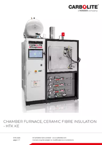
Chamber furnaces of type HTK KE furnaces are insulated with ceramic fibre.
The rectangular design with a front door allows for easy loading and unloading. The HTK range is available in up to six different sizes. The smallest designs with a capacity of 8 litres and 25 litres are typically employed by laboratories for research and development. The 80 litre, 220 litre, 400 litre or 600 litre furnaces are predominantly used as pilot manufacturing systems or large scale production.
The furnaces can be used under a defined Oxygen mixture or 100 % pure Oxygen. The heating elements are CrFeAl, allowing temperatures of up to 1350 °C, or MoSi2 that allow temperatures up to 1800 °C. Inert gas atmospheres are possible; however, poor atmospheric quality must be accepted. Due to the porous nature of the insulation, vacuum operation is limited to a rough vacuum range for short durations.
Application Examples
Ceramic Injection Moulding (CIM), debinding in air, sintering in air
Standard features
- Hydrogen partial pressure operation if requested
- Operation under air or with 100 % Oxygen in the HTK KE
- Precisely controlled vacuum pumping speeds appropriate for powders
- Data recording for quality management
Chamber furnace, ceramic fibre insulation - HTK KE View inside of the HTK KE
- Frame
- Water cooled vessel
- Heating cassette
- Groove for the sealing
- Front door
- Graphite insulation
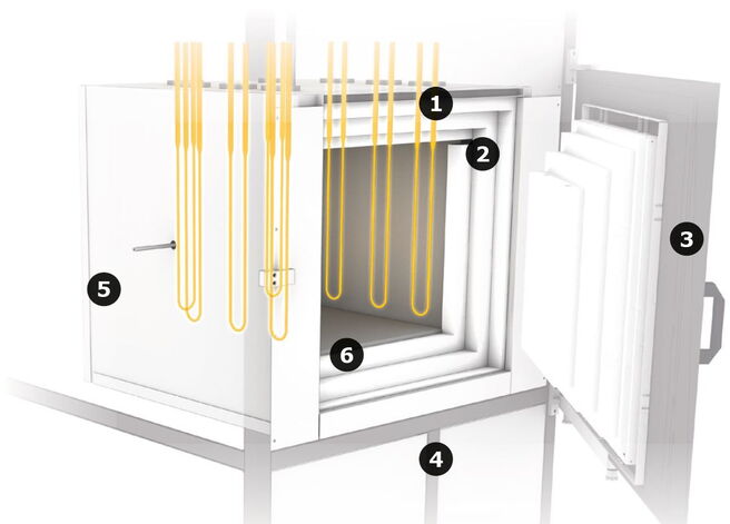
View inside HTK KE
Chamber furnace, ceramic fibre insulation - HTK KE Technical Data
| Insulation material | Dimensions: External H x W x D (mm) | Transport weight (kg) | Usable space | Volume (l) | H x W x D, usable space without retort (mm) | H x W x D, usable space with retort (mm) | Thermal values | Tmax vacuum (°C) | Tmax atmospheric pressure (°C) | -Delta-T, between 500 and 1500°C (K) according to DIN 17052 | Max. heat-up rate (K/min) | Cooling time (h) | Connecting values | Power (kW) | Voltage (V) | Current (A) | Series fuse (A) | Vacuum (option) | Leakage rate - clean, cold and empty (mbar l/s) | Vacuum range depending on the pumping unit | Cooling water required | Flow (l/min) | Max. inlet temperature (°C) | Gas supply | Nitrogen or Argon flow, others on request (l/h) | Controller | |
|---|---|---|---|---|---|---|---|---|---|---|---|---|---|---|---|---|---|---|---|---|---|---|---|---|---|---|---|
| HTK 8 KE/13-1G | Ceramic fibre | 2100 x 1300 x 1100 | 1200 | |
8 | 200 x 200 x 200 | 180 x 180 x 200 | |
1100 | 1350 | ± 10 | 10 | 6 | |
8 | 400 | 20 | 3 x 63 | |
5x10⁻³ | rough or fine vacuum | |
15 | 23 | |
200-2000 | on request |
| HTK 25 KE/13-1G | Ceramic fibre | 2200 x 1900 x 1800 | 1700 | |
25 | 250 x 250 x 400 | 230 x 230 x 400 | |
1100 | 1350 | ± 10 | 10 | 6 | 16 | 400 | 40 | 3 x 63 | |
5x10⁻³ | rough or fine vacuum | |
20 | 23 | |
200-2000 | on request | |
| HTK 80 KE/13-1G | Ceramic fibre | 2300 x 2100 x 2200 | 2000 | |
80 | 400 x 400 x 500 | 380 x 380 x 400 | |
1100 | 1350 | ± 10 | 10 | 8 | |
45 | 400 | 3 x 65 | 3 x 80 | |
5x10⁻³ | rough or fine vacuum | |
40 | 23 | |
200-2000 | on request |
| HTK 220 KE/13-1G | Ceramic fibre | 2500 x 2300 x 2600 | 3000 | |
220 | 600 x 600 x 600 | 560 x 560 x 560 | |
1100 | 1350 | ± 10 | 10 | 10 | |
80 | 400 | 3 x 120 | 3 x 160 | |
5x10⁻³ | rough or fine vacuum | |
60 | 23 | |
1000-10000 | on request |
| HTK 400 KE/13-1G | Ceramic fibre | 2500 x 2300 x 2600 | 3800 | |
400 | 650 x 700 x 900 | 630 x 680 x 900 | |
1100 | 1350 | ± 10 | 10 | 12 | |
120 | 400 | 3 x 180 | 3 x 250 | |
5x10⁻³ | rough or fine vacuum | |
100 | 23 | |
1000-10000 | on request |
| HTK 600 KE/13-1G | Ceramic fibre | 2500 x 2500 x 2900 | 4500 | |
600 | 650 x 750 x 1200 | 630 x 730 x 1200 | |
1100 | 1350 | ± 10 | 10 | 12-16 | |
200 | 400 | 3 x 290 | 3 x 315 | |
5x10⁻³ | rough or fine vacuum | |
175 | 23 | |
1000-10000 | on request |
TF Tube Furnace Range Downloads
Heat Treatment of Steel
The HRF furnace is suitable for hardening and tempering steel by increasing the mechanical resistance through heat treatment. Powerful recirculating air turbines ensure excellent temperature homogeneity for optimum heat distribution, thus complying with requirements according to AMS 2750E Nadcap.