





The Graphite Furnace HTK GR operates with rough and fine vacuum, inert gases such as nitrogen and argon, and reactive gases like hydrogen and carbon monoxide. The Graphite Furnace HTK GR cannot operate in an oxygen atmosphere due to the graphite insulation.
The rectangular design with a front door allows for easy loading and unloading. With seven standard sizes, the HTK GR range grows with your requirements – from the laboratory to production. The smallest designs with a capacity of 8 litres and 25 litres are typically employed by laboratories for research and development. The 80 litres, 220 litres, 400 litres, 600 litres and 1000 litres furnaces play to their strengths as pilot manufacturing systems or in large scale production. And if your process requires more: we can manufacture custom sizes to fit your exact specifications. All models offer flexible process capabilities for demanding industrial-scale applications.
Built entirely around graphite: both the insulation material and the heating elements of the HTK GR are made of graphite. The result: maximum temperatures up to 2800 °C – ideal for extreme heat treatment needs. As an option, a graphite retort ensures a defined gas guiding flow within the unit and improves temperature uniformity to an impressive < ± 10 °C. An optimised gas guiding flow is particularly beneficial in processes with high outgassing rates: the retort protects the graphite components and extends their lifetime.
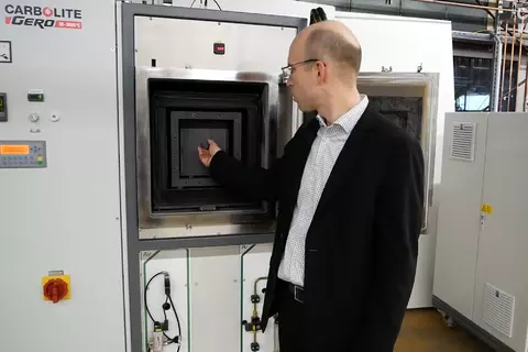
Product Video: Chamber furnace, graphite insulation - HTK GR
Application Examples
Graphitization , Pyrolysis, Siliconization, Sintering, technical ceramics
Standard features
- Graphite furnace, offering the highest possible temperatures
- Hydrogen partial pressure operation if requested
- Precisely controlled vacuum pumping speeds appropriate for powders
- Data recording for quality management
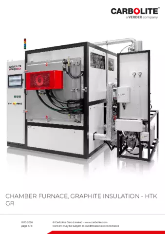
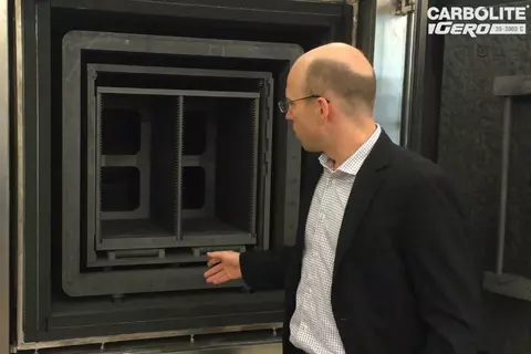
Chamber furnace, graphite insulation - HTK GR View inside of the HTK Graphite Furnace
- Frame
- Water cooled vessel
- Heating cassette
- Groove for the sealing
- Front door
- Graphite insulation
Upon request, the HTK GR can be operated up to 3000 °C. For operation at 3000 °C, the furnace is specially designed with a specific isolation thickness, optimal positioning of the heating elements, and a pyrometer for temperature measurement and control. The pyrometer directly measures the heat radiation by optical methods via a window inside the furnace and is not directly inserted into the furnace.
This measurement principle only works if a sufficient amount of radiation is emitted. The needed radiation is only generated at temperatures exceeding 400 °C. For lower temperatures, a sliding thermocouple is used to control the lower temperatures.
Because of the increasing vapor pressure of graphite, 3000 °C operation is only possible under inert gas atmosphere. Additionally, the high vapor pressure also results in carbon being released to the atmosphere. For carbon sensitive samples, a metallic high temperature furnace must be used.
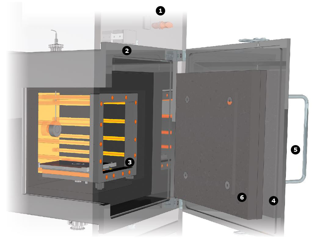
View inside HTK GR
Chamber furnace, graphite insulation - HTK GR Examples
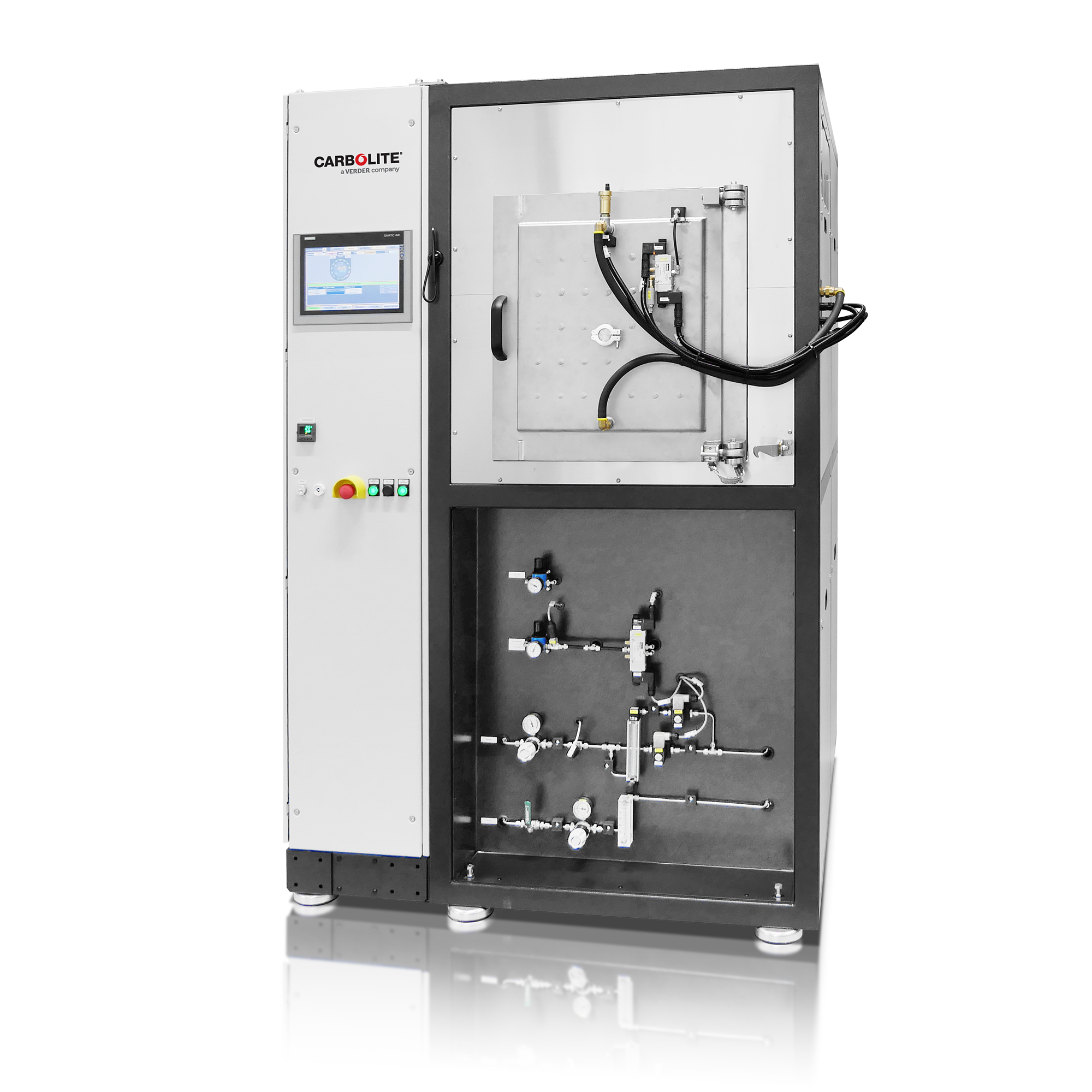
HTK 8 GR/22-1G smart up to 2200°C
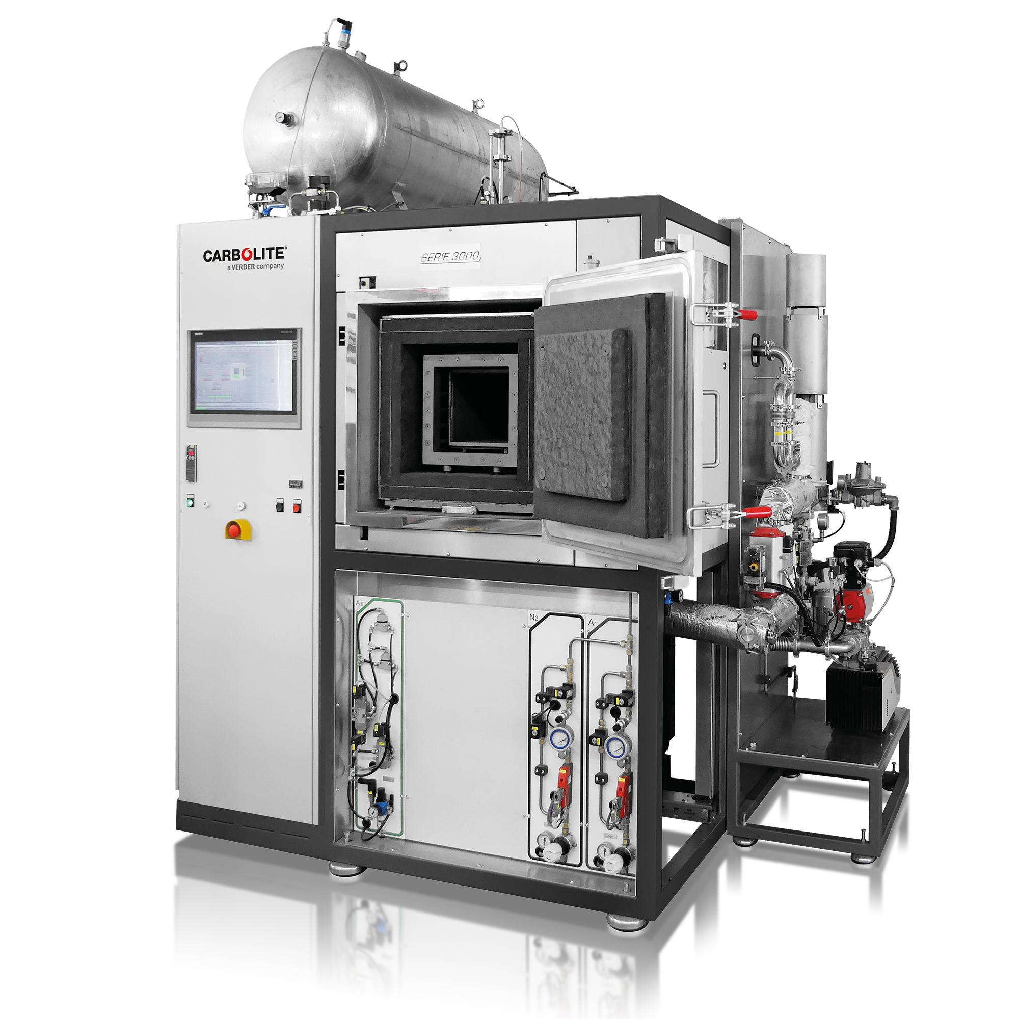
HTK 25 GR/22-1G automatic up to 2200°C with optional pyrolysis package
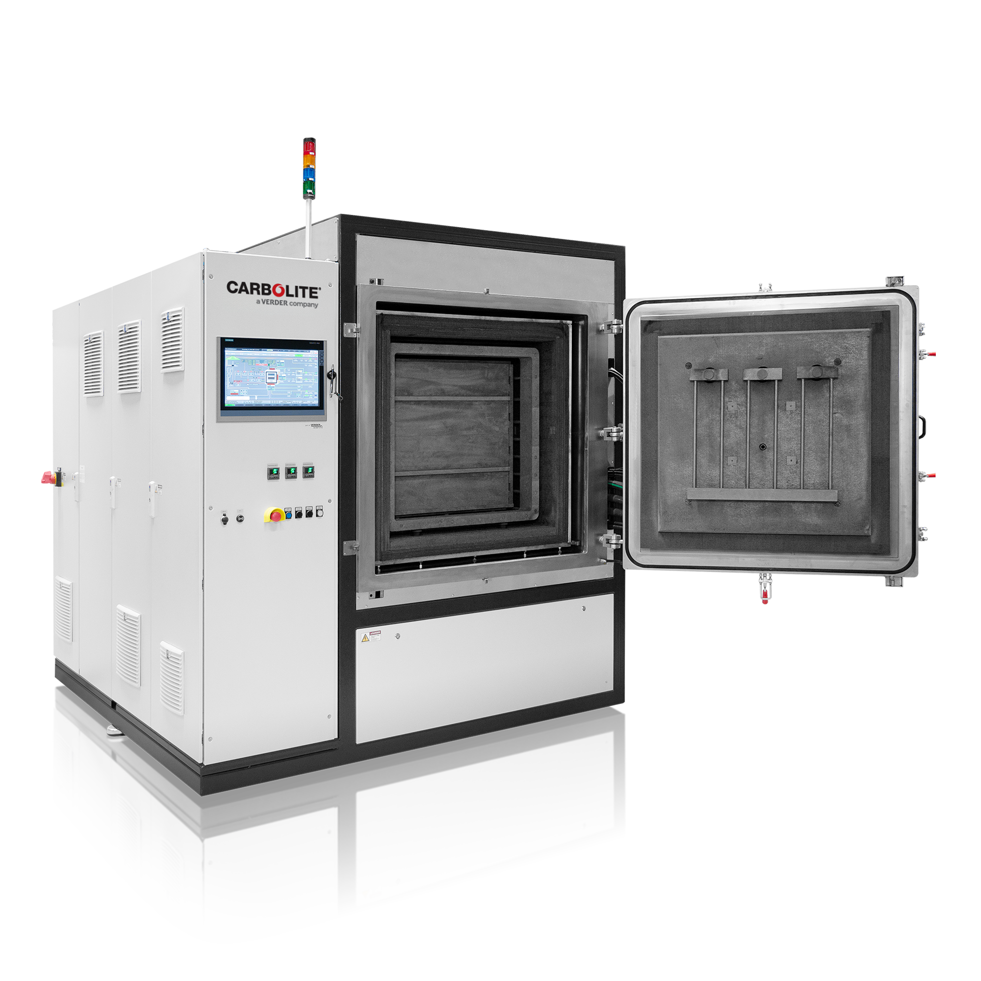
HTK 400 GR/22-1G automatic up to 2200°C
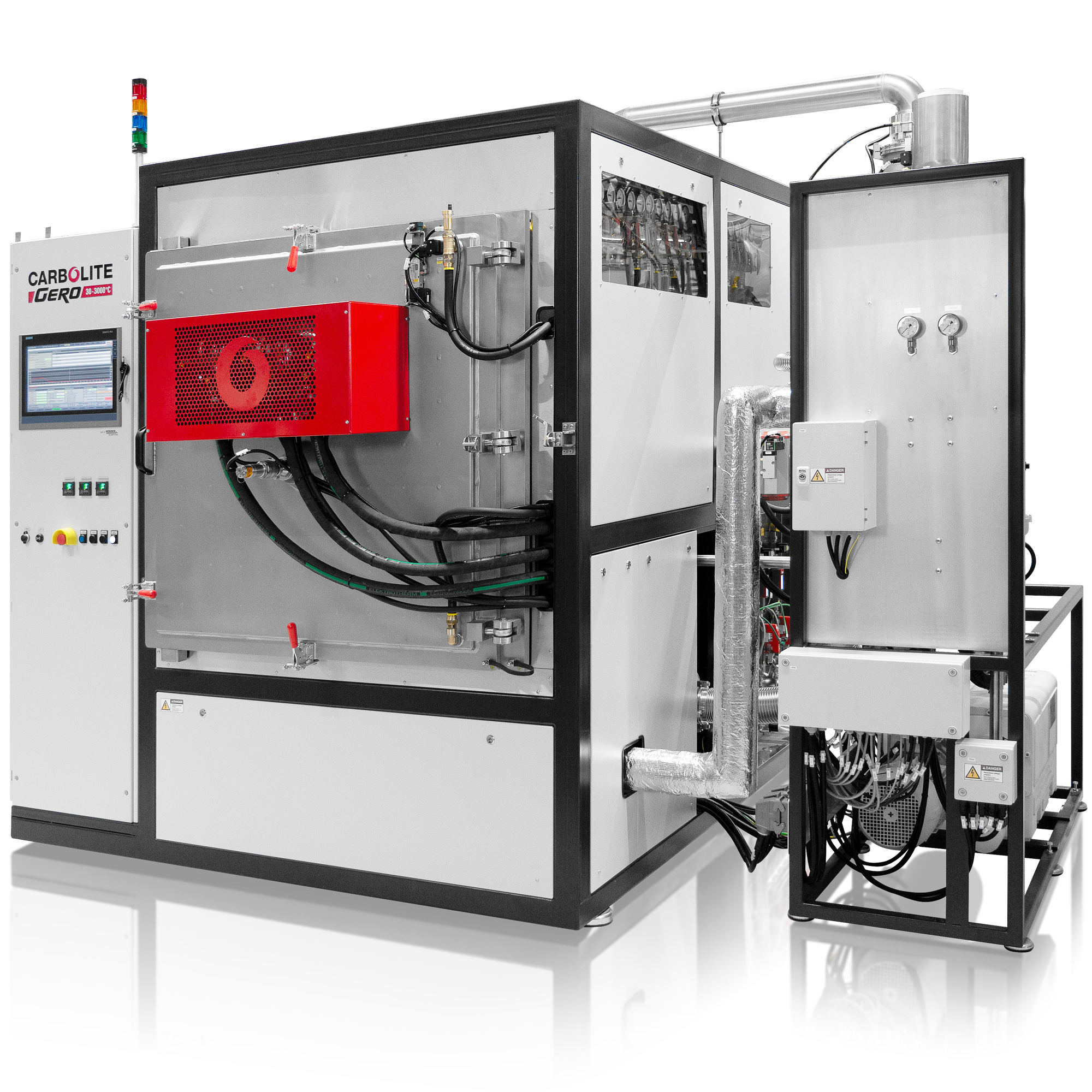
HTK 600 GR/22-1G automatic up to 2200°C with optional fast cooling
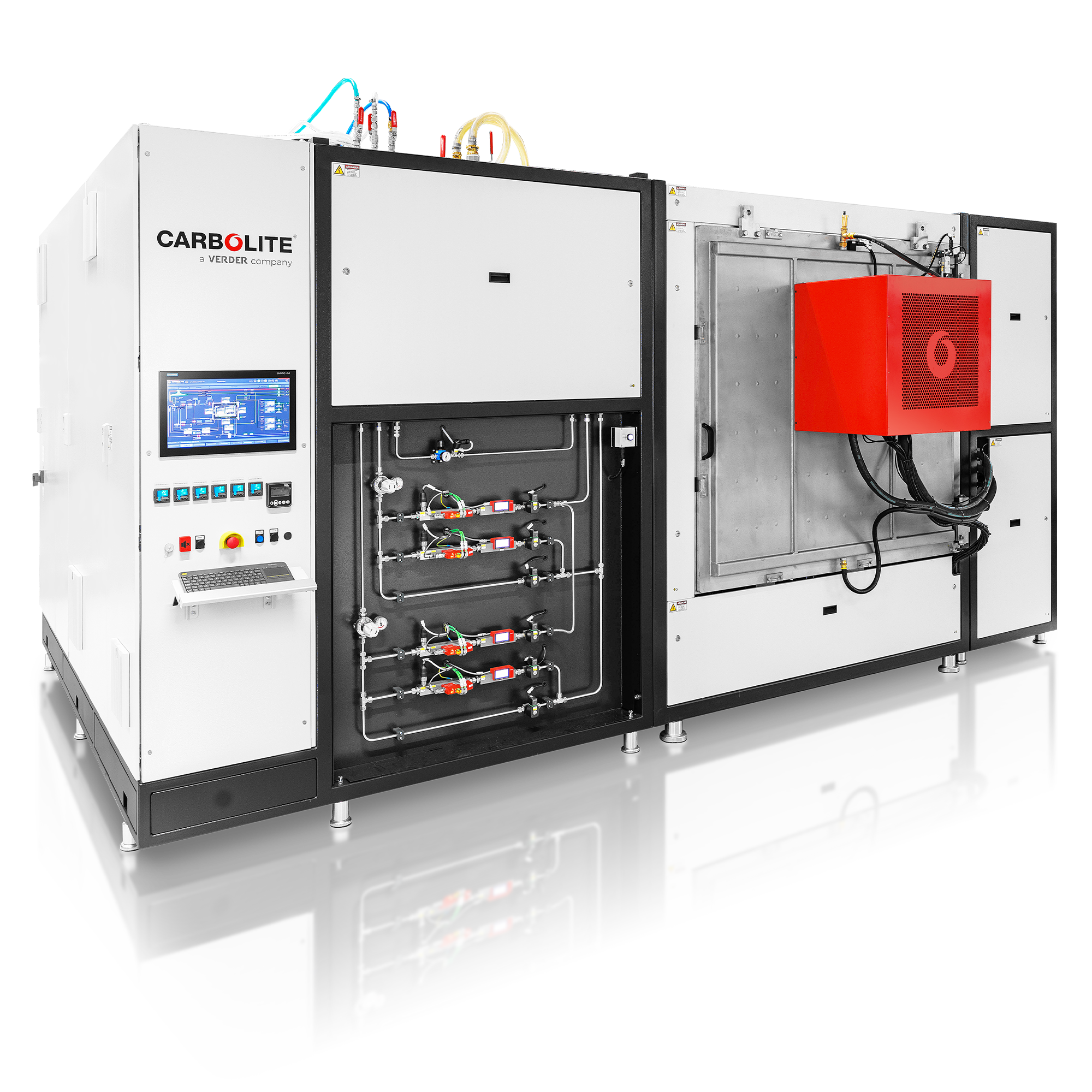
HTK 1000 GR/24 up to 2400°C
Chamber furnace, graphite insulation - HTK GR Technical Data
| HTK 8 GR/22-1G | HTK 25 GR/22-1 | HTK 80 GR/22-1G | HTK 220 GR/22-1G | HTK 400 GR/22-1G | HTK 600 GR/22-1G | HTK 1000 GR/24 | |
|---|---|---|---|---|---|---|---|
| Insulation material | Graphite | Graphite | Graphite | Graphite | Graphite | Graphite | Graphite |
| Dimensions: External H x W x D (mm) | 2100 x 1300 x 1100 | 2200 x 1900 x 1800 | 2300 x 2100 x 2200 | 2500 x 2300 x 2600 | 2500 x 2300 x 2600 | 2500 x 2500 x 2900 | 2850 x 3350 x 4500 |
| Transport weight (kg) | 1200 | 1700 | 2000 | 3000 | 3800 | 4500 | 8000 |
| Volume (l) | 8 | 25 | 80 | 220 | 400 | 1000 | 1000 |
| H x W x D, usable space without retort (mm) | 200 x 200 x 200 | 250 x 250 x 400 | 400 x 400 x 500 | 600 x 600 x 600 | 650 x 700 x 900 | 650 x 750 x 1200 | - |
| H x W x D, usable space with retort (mm) | 180 x 180 x 200 | 230 x 230 x 400 | 380 x 380 x 400 | 560 x 560 x 560 | 630 x 680 x 900 | 630 x 730 x 1200 | 900 x 930 x 1200 |
| Tmax vacuum (°C) | 2200 | 2200 | 2200 | 2200 | 2200 | 2200 | 2400 |
| Tmax atmospheric pressure (°C) | 2200 | 2200 | 2200 | 2200 | 2200 | 2200 | 2400 |
| -Delta-T, between 500 and 1500°C (K) according to DIN 17052 | ± 10 | ± 10 | ± 10 | ± 10 | ± 10 | ± 10 | ± 10 |
| Max. heat-up rate (K/min) | 10 | 10 | 10 | 10 | 10 | 10 | 5 |
| Cooling time (h) | 6 | 6 | 8 | 8 | 12 | 12-16 | > 12 |
| Power (kW) | 26.5 | 60 | 100 | 160 | 250 | 300 | 360 |
| Voltage (V) | 400 (3P) | 400 (3P) | 400 (3P) | 400 (3P) | 400 (3P) | 400 (3P) | 400 or 480 (3P) |
| Current (A) | 3 x 66 | 3 x 90 | 3 x 150 | 3 x 240 | 3 x 370 | 3 x 450 | 3 x 450 |
| Series fuse (A) | 3 x 80 | 3 x 125 | 3 x 200 | 3 x 315 | 3 x 500 | 3 x 500 | 3 x 500 |
| Leakage rate - clean, cold and empty (mbar l/s) | 5x10⁻³ | 5x10⁻³ | 5x10⁻³ | 5x10⁻³ | 5x10⁻³ | 5x10⁻³ | |
| Vacuum range depending on the pumping unit | rough or fine vacuum | rough or fine vacuum | rough or fine vacuum | rough or fine vacuum | rough or fine vacuum | rough or fine vacuum | |
| Flow (l/min) | 40 | 70 | 100 | 150 | 200 | 2200 | 320-370 |
| Max. inlet temperature (°C) | 23 | 23 | 23 | 23 | 23 | 23 | 23 |
| Nitrogen or Argon flow, others on request (l/h) | 200-2000 | 200-2000 | 200-2000 | 1000-10000 | 1000-10000 | 1000-10000 | |
| Controller | on request | on request | on request | on request | on request | on request | on request |
Chamber furnace, graphite insulation - HTK GR Downloads
Heat Treatment / Debinding & Sintering of Additive Manufacturing of Metals, Metal Injection Moulding
Graphitisation at up to 3000 °C - What is it good for?
Graphite is a soft, slippery, greyish-black substance. It has a metallic luster and is opaque to light. Graphite is a good conductor of heat and electricity. Often graphite is simply named carbon. Under inert gas or vacuum graphite is extremely temperature-resistant which makes it an interesting material for high temperature applications.